|
Onsite Wastewater System Compliance
Inspections: Soil System Evaluation
Inspection will often take place at the time of a property transfer and the use of the system by a new owner. The inspection consists of three pieces: the current use of the system and the effects of the use, the condition and performance of the septic tank, and the condition and performance of the soil treatment system. The order in which you inspect the parts of the onsite system may be dictated by the site, but a typical order of completion is to analyze the system use, then the septic tank, and then the soil treatment system. You are not required to address all the defects of the system, but a thorough inspection can be useful in the decision-making process. This module will cover the condition and performance of the soil treatment system and may take up to 75 seconds to load.. Please note that this information was adapted from National Association of Wastewater Transporters, Inc. Inspection of Existing Onsite Treatment Systems. St. Paul, MN.
There should be no sludge moving into the lift station. If there is a build-up of sludge in the lift station or the first section of the trenches, there are probably turbulent conditions in the septic tank, resulting in poor settling. As discussed in evaluating the septic tank, users of the system can often make changes to alleviate turbulence. Check the lift station to see that it's watertight, and inspect its structural integrity just as you inspected the septic tank. Verify that the pump has adequate capacity, taking into consideration friction loss. There should be a quick disconnect set-up. Make sure that there is no standing water in the piping.
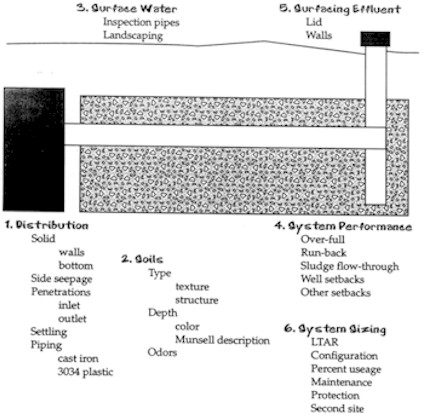
Drop Boxes and Distribution Boxes Inspect the distribution system that brings effluent to the soil treatment area, either drop boxes or distribution boxes. These are good places to check the performance of the tank. Then inspect the distribution system. Verify that drop boxes have solid walls and bottoms. Although drop boxes need not be absolutely watertight, they should be constructed in such a way as to minimize the outflow there. They should have minimal side seepage, so the presence of roots may indicate a problem. The penetration should be solid and free.
If the distribution system is over-full, it's an early sign of problems, possibly due to lack of maintenance or sludge flow-through. There may be sludge in the maintenance box or plugging in the soil system itself. Check these areas.
Examine the piping materials. As mentioned above, cast iron can be a problem because of reactivity with some detergents. Problems with clay and orangeburg pipes are also common, as both these materials are likely to crack, and cracking leads to troubles with roots. If there's excessive root infiltration in the piping, either the soil is too wet, or else the soil is fine, but the piping isn't watertight.
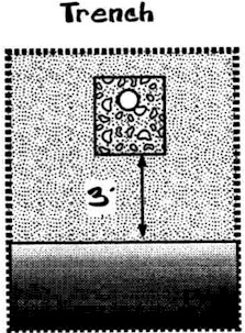
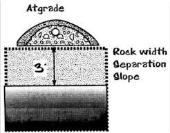
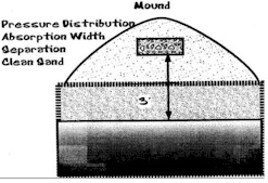
More important than soil type is terms of performance is the depth of the system. Check the distance from the bottom of the system to the limiting layer (bedrock or saturated soil). The system should have been designed and constructed with a "design depth," of at least three feet of soil between the system and the limiting layer, per the standards. Based on current research, three feet of separation will result in excellent treatment. Once the system has been constructed and has begun accepting effluent, the depth to saturated soil will change. The new separation is called the "operating depth" – the actual depth of the water table under the working system. Operating depth is always less than design depth. How much less depends on a number of factors, including surface water drainage and system application rates. But if a system is properly designed with three feet of separation, the operating depth should be sufficient to maintain treatment. That is, from the limiting layer to the bottom of the system, there will be some non-saturated soil.
Take a boring of soil and use the Munsell color book to classify the
soil. This boring should be located near but not in the
system, because the system can change the soil colors, giving a false
reading on the separation depth. If the boring shows wet soils all the
way up to the bottom of the system, that system has zero operating
separation and is not treating the wastewater, which is flowing into
the groundwater and causing problems. There has been a lot of discussion
and debate about the proper operating separation, but as yet there is
no accepted figure for this separation, except that it must be greater
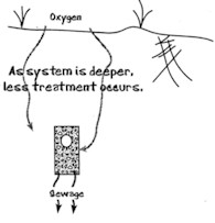
than zero. It is also important that the system not be too deep. "Too deep" means three feet of cover or four feet to the bottom of the system. Soil treatment systems should be relatively shallow to maximize oxygen transfer to the bottom of the system.
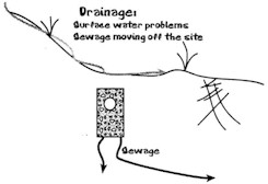
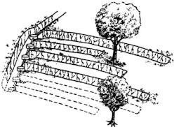
Look at the impact of surface water on the system. Inspection pipes allow visual observation of how much of the system is used and are, therefore, an important component of the soil treatment system. But they must be watertight and have watertight lids to minimize the addition of water to the system. Another issue in terms of surface water is the location of the system in the landscape. Trenches should be located along contours. They should not be located in drainage areas such as the bottom of a drainage way, or in the middle of or transecting a drainage swale.
Soil System Failure – Surfacing Effluent If the soil treatment system is over-full, effluent will come to the soil surface. If effluent is surfacing, the system is failing and is an imminent public health threat. People are creative at hiding sewage! Odor is a great indicator of surfacing effluent. Spongy ground over the top of the system is another indicator. Check for cattails or other landscaping that may hide surfacing effluent. Dye testing is one way to identify failures, but it will miss some failing systems so it cannot be used as the only criterion. There are a number of new dyes that are available for use. They include the use of optical brighteners for the identification of sewage. The process for using brighteners includes collecting a sample on a cotton swab and having the cotton analyzed. This method is still being researched. It is important to identify the cause of the failure. It may be due to plugging of soil pores, sewage flows in excess of the soil's ability to accept effluent, soil compaction, or malfunction or plugging of the distribution system. You may already have found the cause of the problems in your inspection of the septic tank or lift station.
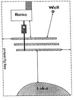
Check well setback distances (and any other setbacks). The most critical, in terms of possible contamination issues, are the setbacks from the well. The setback from the well to the system is based on the construction of both well and system. The distance should be calculated from the absorption area of the well, and based on the type of well and the type of soil treatment system. If the well is shallow, the setback is more critical than for a deep well because of the potential connection between the two systems. Other setback distances, from buildings or property lines, are dictated by local ordinances.
Note the percentage of the soil treatment system that is being used and make a record of it. The users of the system should understand that proper maintenance of their tank and protection of their soil treatment site in terms of drainage, mowing, and avoiding compaction is very important. The system's owners should also make an effort to protect the auxiliary or second site for the system. The texture of the soil determines the size of the soil treatment area. If mistakes are made in design, the system will have a hard time performing properly. The configuration of the system – its layout with respect to the contour of the land – is the second consideration in sizing a soil treatment system.
The system should now have had the use researched and findings noted, the septic tank inspected, and the soil treatment system inspected. The final step in the inspection is completing the reports. Remember, the compliance inspection addresses only whether a system is acceptable or unacceptable; it does not guarantee performance. Also remember that all changes to the design must be signed by the designer. If the inspector makes any changes, he or she is now the designer – a potential liability. The inspector may see mistakes in the design. If these are glaring, a call should be made to the designer to allow the correction of the errors.
Material last reviewed: April 22, 2002 © 2000 The University of Arizona. All contents copyrighted. All rights reserved. |
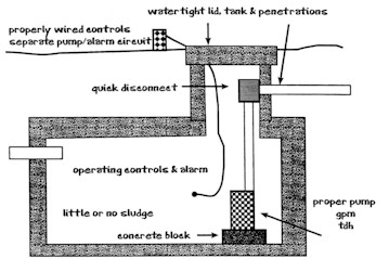 Inspect the soil treatment area. First, inspect how the water
is moved out to the system, including a lift station. You should be
able to access the pump without having to enter the system. The manhole
should be brought to the surface, all electrical connections should
be such that there is no sparking, and there should be a remote shutoff
for the pump.
Inspect the soil treatment area. First, inspect how the water
is moved out to the system, including a lift station. You should be
able to access the pump without having to enter the system. The manhole
should be brought to the surface, all electrical connections should
be such that there is no sparking, and there should be a remote shutoff
for the pump.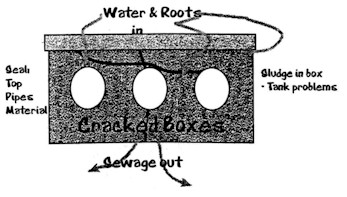 Check distribution boxes for structural soundness and watertightness.
Root infiltration is a definite indication of a problem. Inspect piping
for bows, drops, or ponding water, which indicate possible settling
of the soil.
Check distribution boxes for structural soundness and watertightness.
Root infiltration is a definite indication of a problem. Inspect piping
for bows, drops, or ponding water, which indicate possible settling
of the soil.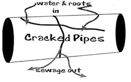
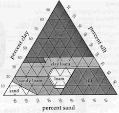 Verify the soil type, its texture and structure. Usually this
is based on the perc rate of the soil, but can also be based on a soil
morphology inspection. Use this information to estimate the proper soil
sizing factor for the system.
Verify the soil type, its texture and structure. Usually this
is based on the perc rate of the soil, but can also be based on a soil
morphology inspection. Use this information to estimate the proper soil
sizing factor for the system.