|
Onsite
Wastewater System
Operation
and Maintenance
prepared by
Dr. Kitt Farrell-Poe, University of Arizona
Please note that this information was adapted from Hoover, M.T., T.A.
Disy, M.A. Pfeiffer, N. Dudley, R.B. Mayer, and B. Buffington. 1996.
North Carolina Subsurface Wastewater System Operators Training School
Manual. Soil Science Department, College of Agriculture and Life Sciences,
North Carolina State University, Raleigh, NC and North Carolina Department
of Environment, Health, and Natural Resources, Raleigh, NC.
This module details operation and maintenance to keep onsite wastewater
treatment systems functioning properly. The following specific components
and systems are discussed:
 Tanks
Tanks
-
Small Onsite Systems
-
-
-
Industrial Onsite Systems
-
Troubleshooting
-
Resources
Tanks
These include grease traps, septic tanks, siphon tanks,
pump tanks, lift stations, and other tanks. Tanks are usually built
from precast reinforced concrete and have 2 ½- to 6-inch wall thickness,
reinforcing bars and welded wire, are sealed with butyl rubber, mastic
(or equal) and are constructed with 3,500 psi concrete. They are usually
premanufactured and transported to the facility.
Some tanks are built in place. The typical masonry septic
tanks are built from 8- or 12- inch blocks in place, poured in place
bottom. A precast top, reinforcing bars, and welded wire, vertical and
horizontal reinforcement complete the tank. Then each core is filled
with concrete and the inner walls are plastered with concrete.
Septic Tank
The purpose of a septic tank is to provide solids' separation,
detention time, a means for solids'; removal, additional storage capacity,
and some wastewater treatment. Several types of septic tanks and design
components may be used. Common tanks include pre-approved tanks made
of reinforced concrete, masonry built-in-place tanks, fiberglass tanks,
and polyethylene tanks. At-grade access openings, a vented baffle wall,
and outlet sanitary tee are other important parts of the tank. Most
critical, however, is that the tank is structurally sound, sealed, and
watertight, and that all components are intact and functioning.
Typical operation and maintenance procedures
To keep a septic tank functioning properly, the following must be done:
- Frequent inspection. Look at the tank routinely to detect
damage such as cracks, breaks, or deterioration, leakage, indicating
loss of watertightness, improper tank use, and settlement or flotation
of the tank.
- Maintain proper ventilation.
- Keep the location accessible.
- Remove solids and scum as needed. Solids should be removed
from septic tanks when the solids' level reaches 25 to 33 percent
of the liquid capacity of the tank.
Grease Traps
Grease traps provide grease and solid separation, heat
dissipation, means for grease removal, and additional storage capacity.
The parts of a grease trap (shown in Figure 1) are the same as a septic
tank except for larger access openings and deeper outlet sanitary tee,
and they are not designed for toilet wastes. Operation and maintenance
of grease traps are also the same as for septic tanks except with the
added need to frequently remove grease and solids. This can be done
by skimming or pumping. Remember that grease traps should receive only
kitchen waste.
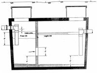
Figure 1. A schematic diagram of a grease trap.
Source: Burks, B.D. and M.M. Minnis. 1994.
Onsite Wastewater Treatment Systems. Madison, WI: Hogarth House,
Ltd.
Pump/Siphon Tank
The primary purpose of the pump/siphon tank is to provide
a location for the distribution device. Other purposes include additional
storage capacity, some pretreatment, and some solids separation in the
pump tank. Pre-approved pump tanks differ from septic tank design in
that pump tanks have larger outlet access openings, are constructed
without a baffle, use the full tank depth, and have emergency storage
capacity and anti-floatation provision. Follow; the same operation and
maintenance procedures for pump and siphon tanks that are outlined for
septic tanks. Be sure that only septic tank effluent enters the pump
tank.
Lift Station
A lift station typically collects raw sewage and provides
pumping device location, additional storage capacity, a mechanism to
pump uphill or long distances, and promotes centralized collection system.
In addition to the operation and maintenance procedures for septic systems,
lift stations should be washed down and cleaned regularly. Pipe connections
should also be checked routinely.
Procedures for Operation
and Maintenance of Tanks
- Determining watertightness - visual inspection, 24 hour
in/exfiltration test, low pressure air test, excessive pump run times,
or doses (see Appendices).
- Measuring solids level - visual inspection, column sampler
(sludge judge), or probe penetration identifying the solids level
and grease level (see Figure 2).
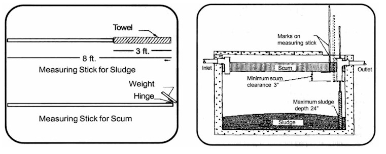
Figure 2. (Left) Homemade devices for measuring sludge and scum.
Source: Hassinger, E. and K. Farrell-Poe. 2000. Maintaining your septic
tank. Arizona Cooperative Extension fact sheet AZ1160. University of
Arizona, Tucson, AZ. (Right) Procedures for measuring the accumulation
of sludge and scum layers in a septic tank. Source. Schwab, D., J.H.
Armstrong, and S. Harp. Septic tank maintenance. OSU Extension fact
sheet No. 1657. Oklahoma State University Extension.
Typically tank problems are caused by traffic loads over nontraffic-bearing
tanks, inaccessibility of tanks, component deterioration and damage,
or excessive water use. For proper tank inspection you need steel-toed
boots, rubber gloves, a flashlight, a mirror, a tape measure, a sludge
judge (or other sampler), a manhole hook, and a shovel.
Small
Onsite Systems
Many small onsite systems that serve single homes need
to be properly operated and regularly maintained by a trained and certified
onsite system operator. This need certainly exists for pressure distribution
systems such as low pressure pipe (LPP) systems, drip irrigation systems,
low pressure distribution (LDP) systems, pressure-dosed Wisconsin at-grade
systems, sand mound systems, and pressure-dosed sand filters. Pump to
D-box systems and pressure manifold systems also should be maintained
by a certified operator since they use pumps, floats, electrical controls,
and an alarm system. Other alternative and innovative systems such as
aerobic treatment units, constructed wetlands, and disinfection systems
also require regular maintenance and should be operated by an onsite
system operator.
Operation & Maintenance
(O&M) Activities
The specific operation and maintenance activities that
an operator needs to be concerned about at a single-family onsite system
will vary depending upon the complexity of that system. However, these
activities can be organized into five categories regardless of the type
of system. These categories include preparing, monitoring, measuring,
maintaining, and sampling activities. Of course, the types of system
components used at a particular site will determine which specific activities
are included in each category. An example follows of the O&M activities
for a system that has a pressure-dosed sand filter followed by an in-ground
pressure distribution system. (Table 1). The system
components include a septic tank, pump tank, pressure-dosed buried sand
filter, a second pump tank that receives the sand filter effluent, and
a pressure distribution system such as a low pressure pipe system or
low pressure distribution system installed in very shallow trenches
in the soil.
- Preparing for the O&M of an onsite program. One of the first
things the operator should do is make sure he or she knows where all
the parts of the system are located. The system design or permit should
include design specifications for the pressure distribution networks
(two here - one in the sand filter and one in the soil). The operator
will compare the system performance against these design standards
to determine if the pressure distribution system is working correctly.
On the basis of the types of components in the system, the operator
should then develop an O&M plan. Be aware that the type or frequency
of inspections might be specified in a system Operation Permit issued
by the appropriate regulatory agency. Finally, the operator should
prepare a safety plan before beginning other O&M activities.
- Monitoring activities. The operator should monitor specific
system components to make sure they're working properly. Many of these
monitoring activities are conducted to answer questions that require
only a simple yes or no. For instance: Is the wastewater at the correct
level in the septic tank and pump tanks? Are the tanks and risers
watertight? Are the pumps, floats, valves, electrical controls, and
alarms functioning properly? Are there any breaks in the pipe network?
- Measuring activities. Regular measurements need to be made
of the sludge and scum levels in the septic tank, the clarity of
the
pump tank effluent, the pump run time for a dosing event, and the
settings for any gate valves used to adjust pressure head in the
distribution
system. Then the dose volume and pump delivery rate should be calculated
and compared to the design specifications. These measurements and
calculations need to be recorded on the O&M evaluation form so that
the performance of the system can be evaluated over time. This provides
you, the operator, with specific information to help properly maintain
the system.
- System maintenance activities. Since there is such a broad
range of possible maintenance activities, the operator must be very
careful to specify the activities for which he or she will be responsible.
These should be clarified in the contract with the homeowner. Some
activities, such as adjusting the pressure head or adjusting the tether
lengths of floats, are fairly straightforward. Others, such as landscaping
to divert water from tanks or sealing tanks after they've been installed,
can be quite expensive and disruptive to the property at the site.
The operator and homeowner both need to have a clear understanding
about which maintenance activities are the responsibility of the operator.
- Sampling activities. The last category of activities that
an operator might be responsible for is sampling. Sampling and analysis
of the sand filter effluent would help the operator evaluate the performance
of this pretreatment unit. Sampling of ground water monitoring wells
might also be a responsibility of a subsurface system operator. However,
ground water monitoring would more likely be required at sites of
large onsite systems than at single-family homes.
Table 1. Operation and maintenance (O & M)
activities for an onsite system consisting of a sand filter followed
by a low pressure pipe distribution system.
Preparing Activities:
- A diagram showing the location of all system components.
- A list of system design specifications such as design pump delivery
rate, design dosing volume, design pump run time, and design pressure
head.
- An O&M plan based upon conditions specified in the Operation
Permit.
- A safety plan for these O&M activities.
Monitoring Activities:
- Wastewater level in the tanks.
- Watertightness of tanks, risers, and pipe connections at tanks.
- Pumps, floats, valves, electrical controls, and alarm operation.
- Pumping frequency from impulse counters and elapsed time meters.
- Sand filter surface for wastewater ponding.
- Physical integrity of the pipe network.
- Vegetative growth over drainfield.
- Surface water diversion upslope of the system.
Measuring Activities:
- Sludge and scum levels in septic tank.
- Sludge level in pump tank and effluent clarity.
- Pump delivery rate at the design pressure head.
- Dose volume.
- Number of turns that gate valves were opened when pressure head
was set.
Maintaining Activities:
- Landscaping to divert water from tanks, filter, and drainfield.
- Seal tanks to prevent infiltration.
- Pump solids from tank as needed.
- Flush solids, anaerobic slimes, and roots from laterals.
- Adjust float tether lengths to modify dosing volume, as needed.
- Adjust pressure head to design specifications.
Sampling Activities:
- Periodically sample sand filter effluent and septic tank effluent
for BOD (or COD) and suspended solids.
Step-by-step procedures for a
site visit at a pressure-dosed system
- Familiarize yourself with the system. In order to prepare
for a site visit, the first thing you need to do is obtain a copy
of the permit, specifications, drawings, and O&M requirements. These
may be obtained from the permitting agency, the designer, or owner.
This first step gives you information on what you're monitoring, the
location, and O&M requirements in order to calculate time and amount
of money needed for the contract. You should also develop a form for
recording information from the site visit.
- Carefully plan and compose contracts. In writing your contractual
agreement with the homeowner, you need to spell out what you will
be responsible for and understand what you can do with or without
permits. Make sure the homeowner understands the agreement. Initially,
the permitting agency should provide some assistance in educating
the homeowner. Acquaint yourself with the system and carry any system
information and past date to the field for review.
- Locate the septic and pump tanks.
- Begin monitoring the system by locating the tanks. Be sure to
disconnect the power to the pump before you begin so the pump
will not activate until you are ready. Then run water into the
pump tank and restore the power to the control panel. Watch and
listen for activation of the pump by the control float switch
or listen for the pump or a substituted indicator buzzer with
the aid of a piggyback. (When running water into the pump tank
leave air space or be sure to connect with a suitable backflow
preventor.)
- Next you are ready to locate the lateral line ends, which should
be found in a six-inch pipe with a cap or in a valve box. Check
the pump tank.
- When the control float activates the pump, disconnect the power,
stop the water, and measure the effluent level. This information
is needed for dosing volume calculation and should be recorded
as "Float-On" level. After you have recorded the effluent level,
continue to run water into the pump tank until you have enough
water in the pump tank to flush out lateral lines at a later time
in the monitoring visit.
- While the pump tank fills, you can complete other aspects of
the evaluation, such as evaluating septic tank sludge level, effluent
quality, scum layer activity, and nonbiodegradables. Listen and
look for evidence of infiltration (especially between the tank
and riser) and plumbing leaks.
- Follow this same procedure when evaluating the pump tank, except
for the scum layer. Raise the alarm float to test the function
of the float, alarm light, and audible sound. This should be done
at the site of the remote alarm inside the home.
- Check the head pressure.
- With the specifications and/or the permit, note which lateral
lines to use to regulate the design pressure heads. As a minimum,
check the head pressure in the uppermost lateral in each subfield.
It is important to set the pressure head correctly so your field
measurements can be usefully compared with the design requirements
and previous monitoring information.
- Place clear plastic tubing on the distal end of the appropriate
laterals and mark the design pressure head.
- While the pump is running, adjust the control valves to regulate
the system to the design head.
- Stop the pump and take an effluent level measurement for the
pump delivery rate calculation and record under "Pump On."
- Now you are ready to start pumping. Run the pump for a specific
time, at least for five to eight minutes.
- Stop the pump and re-measure the effluent level at the end of
the specified time and record as "Pump Off."
- Calculate dosing rate and volume. To calculate the pump delivery
rate (PDR) in gpm, subtract your beginning ("Pump On") effluent level
from the ending ("Pump Off") effluent level, multiply the difference
by the number of gallons of effluent per inch or foot in the tank,
then divide by the number of minutes of pump run time in order to
get delivered PDR. Compare the delivered PDR to the design PDR to
help determine the system performance. If the measured PDR was above
the design PDR, look for damaged and broken piping. You will take
one more measurement at a later time at the float-off level. This
measurement must occur while you are flushing laterals. The float-off
level and float-on level are used to calculate the dosing volume (difference
between float on and off x gallons/inch or feet). This is especially
useful with a pump counter to determine hydraulic loading of the system.
- Flush the laterals.
- Mark and count the turns as you open the control valve. Record
the position of the valve so you can reset it after flushing the
laterals and for future reference on subsequent monitoring visits.
Valve adjustment is another indicator of the system performance.
For example, the need to continually turn the valve down to regulate
the pressure head is an indication of clogged holes in the laterals
or of tampering with the system.
- Remove the clear tubing used for the pressure head adjustment.
- One lateral at a time, with the control valve wide open, remove
the end cap and flush each lateral using the existing pump tank
effluent. The effluent should flush back into the valve box, making
contact with gravel in the trench, and there should be no discharge
to the ground surface.
- Run the pump until the effluent clears from each lateral. Then
go to the next lateral. Be sure to note anything of interest on
the report form such as root masses, non-biodegradables, restricted
flow, or a blockage resulting in no flow.
- You are now ready to reposition the control valve to the adjusted
position and if necessary recheck your pressure head.
- Check other mechanical components. In addition to what you
have already noted and recorded, you will also want to do the following:
- Open and close the valve in the pump tank to clear any accumulated
debris and check the function while looking for leaks at the unions.
- Check for a vent or anti-siphon hole.
- Listen and feel for functioning check valve.
- Note the type of pump and check to see that it is firmly seated.
- Note the tether length on the control float and check for lifting
rope.
- Note whether the pump was submerged at the float-off effluent
level. (Corrosion is minimized when the pump is kept submerged).
- You are now ready to evaluate the NEMA 4X enclosure by making
sure it is watertight and not damaged. Make sure all indicator
lights and toggle switches function on the control panel and that
conduits are sealed (preventing sewer gases from entering the
box). If using piggyback plugs, look for corrosion, overheating,
bent or broken plugs and any other damage. Locate all the lateral
end caps, making sure they are centered in the valve box, and
have been flushed out.
- Check the disposal field. It is important to note if any
effluent surfaced during the evaluation of the system so that you
can notify the homeowner and the health department. Note the condition
of the drainfield, looking for any settling over the trenches or ponding
of surface water. Make a note of the type and density of vegetation
over the drainfield (i.e., whether it is grassed or wooded) and whether
it is maintained or needs attention. If you notice settling over the
trenches, you may lightly till and mound the backfill in order to
shed water. If the understory growth over the drainfield is out of
control, you must thin it by hand. Keep the drainfield areas clear
to minimize the possibility of roots restricting the flow and altering
even distribution in the drainfield by growing in or around the lateral
pipe. For maintenance on wooded sites, copper sulfate dosed from the
pump tank my be an option. However, you should check on this with
the permitting agency. If an extreme root problem exists, you may
consider redesigning the hole pattern, which involves excavating over
the lateral and redrilling the holes. A permit is required for this.
After drilling through the top and bottom of the pipe, plug the hole
on the upper side of the pipe. Another vegetation problem could exist
if the root systems were cut during installation, thereby causing
trees to die and fall, exposing the lateral end that was placed under
the root system. There is the possibility of tree limbs penetrating
the ground surface when the tree falls, resulting in damage to the
piping and causing the system to malfunction.
- Mechanically cleaning the laterals. Even though you may flush
the laterals each visit, slimes and sludges may build up and block
holes, altering the distribution in the drainfield and dictating mechanical
removal of accumulated solids. In open sites where tree roots are
not a problem, mechanically cleaning the lateral lines with the use
of a plumber's snake and brush should return the system back to design
pump delivery rate. (Please wear gloves for hygienic safety.) This
may be done by cutting the lateral at both ends, pushing the snake
through the lateral, attaching a brush to the snake, and pulling the
brush back through the lateral. You will be able to see the sludge
that was removed.
- Additional inspection and general maintenance. Homeowners
can damage the system by mowing and by land-disturbing landscape activity,
so be sure to note and replace broken pipes and fittings. With routine
monitoring, homeowners should be aware of the system's location and
avoid damaging it. They should not build additions, detached garages
and workshops, pools, fences, basketball courts, etc. over the system
and drainfield. A permit is required if the drainfield has to be replaced.
Be sure to watch for underground utilities such as cable, telephone,
and community water and power. Stay on top of the system, note the
small problems and correct them early before they become major, and
keep good records of what you do.
Industrial
Onsite Systems
This section provides a definition of industrial process
wastewater, a discussion of the most common industrial process wastewaters,
associated treatment devices and design criteria, maintenance, and control
points, and a discussion of the operational and regulatory problems
associated with industrial process wastewater.
Per north Carolina General Statute 130A-334, "industrial
process wastewater means any water-carried waste resulting from any
process of industry, manufacture, trade or business". Most businesses
only generate wastewaters from restroom facilities and do not generate
any process wastewaters and are thereby excluded from this definition.
Some businesses, such as restaurants, meat markets, and beauty shops
are considered domestic due to the domestic characteristics of their
discharge.
Common industrial process onsite wastewater treatment
facilities include carwashes, dog kennels, veterinary clinics, dentists'
offices, doctors' office with x-ray facilities, and coin-operated laundromats.
Based on a review of currently operating systems the most common problems
and remedies for the successful operation of these facilities are as
follows:
1. Carwashes. The operator should remove grit
and sand from grit chamber at 50% of depth of standpipe. For standard
oil/water separators, the oil should be removed before it reaches a
depth of more than 12 inches from the surface level. If recognizable
oil is observed in the septic tank, distribution box, drainfield laterals,
or surfacing, the operator should observe a sample of the effluent for
oily emulsions. Emulsified oils may require a change in the detergents
at the carwash.
2. Dog kennels. It is recommended that the effluent
pipe be blocked while removing and cleaning the effluent filter to prevent
mats of animal hair from discharging through the effluent pipe. Dog
solids degrade very slowing and will rapidly fill the tank. Disinfectants
should not be washed to the system; instead, they should be applied
after washdown is complete.
3. X-ray facilities. Fixer and developer must not
be discharged. Rinse water may only be discharged after silver recovery
treatment. The silver recovery cartridge should be replaced at 50 percent
utilization.
4. Laundromats. Small mesh (-200 micron) filter
screens must be in place.
In addition to these common treatment systems which can
operate successfully without extensive pretreatment, there are several
problematic and uncommon industrial process onsite wastewater systems
currently permitted. These include bakeries, slaughterhouses, seafood
processors, egg hatcheries, organic chemical manufacturing, solid waste
transfer stations, funeral home embalming facilities, metal machining,
and electroplating businesses. The problems encountered with these wastewaters
include:
1. Excessive organic content (high BOD) which can cause
excessive biomat formation and premature surface failure. This problem
often occurs at slaughterhouses, seafood processors, egg hatcheries,
solid waste transfer stations, and bakeries.
2. Pass-through of pollutants which may contaminate groundwater
some of which may also be characterized as a hazardous waste, i.e.,
organic chemical manufacturing, metal machining, and electroplating.
By federal law, industrial process wastewaters which may be characterized
as hazardous waste cannot be discharged to subsurface systems under
any circumstances.
3. Biological interference with the pretreatment system
or subsurface treatment system. This problem often occurs as a result
of funeral home embalming.
4. Solid or viscous substances which can cause obstruction
in the pretreatment or subsurface disposal system, i.e., eggshells from
hatcheries, hair from slaughterhouses, scales from seafood processors,
sesame seeds for a bakery.
These types of wastewaters may require specialized pretreatment
(i.e., aerobic treatment, chemical precipitation, custom filters, dissolved
air flotation, air stripping) prior to subsurface discharge. These specialized
pretreatment systems may require an operator who also has wastewater
treatment plant certifications, industrial pretreatment operator certifications,
or manufacturer certification. Also, these atypical systems, often have
effluent monitoring or groundwater monitoring requirements.
In addition to reviewing the previously mentioned items
during inspections, it is important to determine if the industry has
changed its discharge strength or flowrate. To help determine if significant
changes are occurring which may effect the operation of the treatment
system, an industrial inspection form has been developed by North Carolina
and is included in the appendices. Inspection forms developed for individual
components of the wastewater treatment system should also be completed.
These inspection forms should be part of the operator's report to the
local health department.
Troubleshooting
Troubleshooting is a systematic means for identifying
problems in small onsite wastewater treatment systems. The 9-step procedure,
outlined below, should help find and correct most system malfunctions.
- Locate permit, approval form, system design, and system set up,
including pressure head, deliver rate, and other factors.
- Determine the nature of the malfunction or problem. Is it ...
- Surface discharge (Over septic tank, pump tank, D-box, or drainfield)?
- Backing up into the house?
- Slow-draining house fixtures?
- Ground water contamination?
- Seasonal "wet weather" or continuous problem?
- Flowing sewage or small wet spot that flow back into the ground?
- Immediate failure or failing after a number of years?
- Determine wastewater flow:
- Check permit for design flow.
- Determine water consumption and actual flow into the system,
which are not the same.
- If meters are available, check water bills or check meter yourself
over a month.
- Is there an abrupt increase in flow and what is the flow pattern?
The flow may be coming from leaking plumbing, added appliances,
or changing water use habits in the home.
- Excess flow may be from a purposeful addition such as a sump
pump, rain spouts, foundation drains, a heat pump, a water softener,
a swimming pool, an ice machine, industrial waste, commercial
water, or flow drains.
- Observe topography and surrounding properties, including:
- Density of development. Lot size and the shape of the
property may influence what can be done to repair the problem.
- Performance of surrounding systems.
- Landscape position. Systems at the base of a hill, downhill
from a large watershed, swale, road, or ditch or with water added
from the surface or subsurface may have wet weather failure.
- House location relative to the system. Water from roofs,
gutter drains, patios, and driveways may cause problems during
wet weather.
- Slopes. Is it a complex sloping area?
- Cut areas. Is the system installed in an excavation area?
Are cut areas downslope of the system?
- Location and types of trees near the system. Tree roots
may cause clogging in conventional systems and hole clogging in
low pressure pipe systems. Check for saturation in trenches in
front of and behind the tree. Undesirable tree species include
willow, willow (water) oak, elm, tulip, poplar, some maples, and
sweet gum. These trees should be cut off and their stumps treated.
Hickory, white oak, dogwood, and sourwood trees should be left.
- Evaluate soil properties.
- Determine soil properties. Are the particular soil properties
likely to cause the problem?
- Determine the particular loading rate for the soils.
This is a function of soil depth, soil wetness, morphologic properties,
loading rate, trench bottom, abrupt textural changes in profile,
loading rate and area, and linear loading rate.
- Information from the soil evaluation determines if site can
be used for repair installation.
- Investigate functioning of distribution devices.
- Uncover the D-box and check its condition. This will
tell which way to look for the problem, either toward the septic
tank or toward the drainfield.
- Answer the following question:
- Is effluent flowing from the septic tank toward the D-box?
- Is effluent overflowing the D-box (higher than the outlets)?
- Are there excessive solids in the D-box?
- Is one or more line receiving too much flow?
- Check the outlet of the tank:
- Is it full of solids and grease?
- Is the outlet working properly holding back solids, paper,
and grease?
- What is the depth to tank, which indicates if the drainfield
is too deep?
- Check the inlet of the tank:
- Check the pressure distribution:
- How's the water level?
- Is the pressure head high?If so, holes may be clogged.
- Is the pressure head low? If so, there may be a leak caused
by a broken pipe or the gate valve may be clogged.
- Is the actual pump delivery rate the same as what the system
was designed to deliver?
- Check impulse and elapsed time pump counters.
- Check for proper operation of pump, controls, float and
alarm.
- Find trenches and determine level of ponding by doing the following:
- Putting observation tubes in trenches.
- Determining if ponding is permanent or periodic.
- Checking for overload on one part of the system.
- Determining if soil capability varies across the site.
- Finding depth of lines. Are they too deep, in shallow water
table, or picking up perched water?
- Noticing if lines run into a hill rather than on a contour.
Are they too shallow or on uneven topography?
- Looking to see if gravel is in-filled with soil, which could
be caused by discharge over certain holes or root mats.
- Determine wastewater absorption rate into the soil (must have a
water meter at the home).
- Use water meter records to establish the daily water use at
the home.
- Put observation tubes in trenches.
- Mark level of ponding in the observation tubes.
- Use NO water for 8 hours. Turn water off to the house and let
it sit. Effluent level in the trenches will go down some. After
eight hours measure how far the effluent level has receded in
the trenches. Mark this in the observation tubes.
- Check the initial water reading on the water meter.
- Have someone turn on water and let it flow until the effluent
level in the trenches rises back up to the previous level when
the water was turned off. Check this level against the marks you
made earlier in the observation tubes.
- Read the water meter again and determine the amount of water
that flowed into the system. This is the amount of effluent that
the soil can absorb during an 8 hour period of use.
- Determine the amount of effluent absorbed in the soil in 1
day (= amount absorbed in 8 hours X 3) and calculate the system
overload. % overload = [(avg. daily water use - amount water absorbed)/average
daily water use] X 100%. If the system overload is less than 35
percent, then water conservation should correct the problem. If
the system overload is greater than 35 percent, then water conservation
will not solve the malfunction.
- Evaluate available information and determine most likely causes
of failure.
 Resources Resources
- Pipeline. 1995. Maintaining your septic system – a guide for
homeowners. Vol. 6, No. 4. National Small Flows Clearinghouse. Morgantown,
WV. [PDF]
Material last reviewed:
April 27, 2004
© 2000 The University of Arizona. All contents
copyrighted. All rights reserved.
|